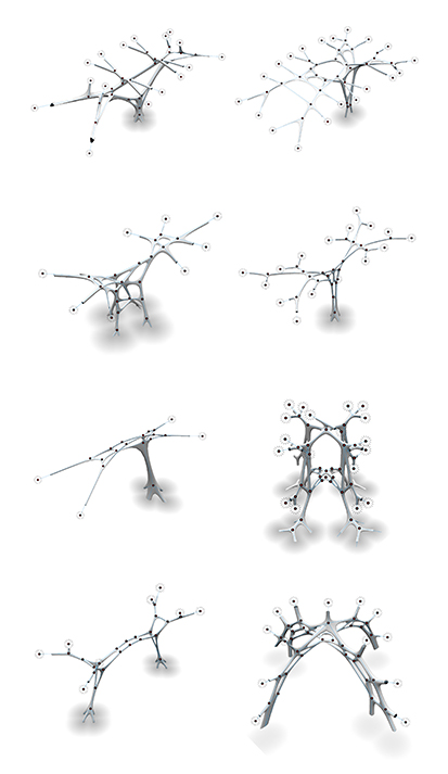
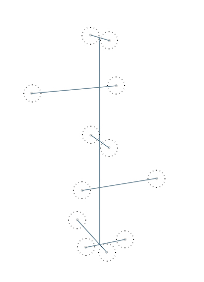
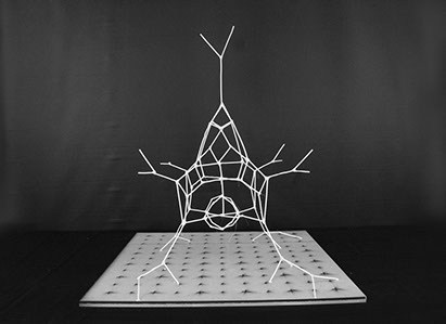
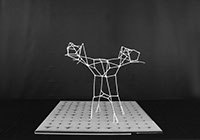
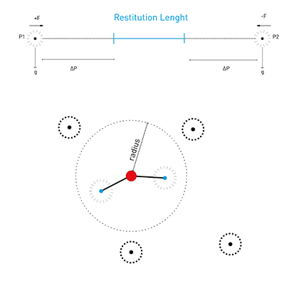
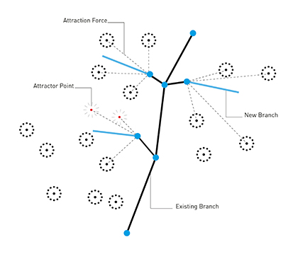
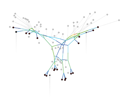
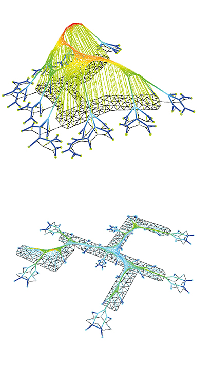
DNA DISCRETE NETWORK ASSEMBLY
SHAJAY BHOOSHAN STUDIO PHILIPP SIEDLER FEDERICO BORELLO BEGUM AYDINOGLU
DRL 2015/2017 ARCHITECTURAL ASSOCIATION
COMPUTATIONAL RESEARCH Material System
1752. Giambattista Suardi proposes a geometrical pen for the design of curves from the compound motion of several gears. 1791. George Adams publishes his Geometrical and Graphical Essays, including the first description of Suardi’s machine in English. 1799. Gaspard Monge publishes ‘Geometrie descriptive’, a systematic approach to the visual calculation of curves, surfaces and their intersections. 1813. John Farey introduces his mechanical ellipsograph. 1822. Charles Babbage begins work on his difference engine. 1838. C. Protot publishes his Cours special d’architecture, ou Leçons particulieres de geometrie descriptive. 1850. F.C Penrose introduces his helicograph. 1871. Edward Burstow, an architect, advanced ellipsograph. 1883. Antoni Gaudi begins his designs Familia, with pervasive use of ruled surfaces. 1884. Hermann Holerith creates a computer based on electromechanical principles, ending the age of mechanical calculation machines. 1889. Louis Monduit Publishes his Traite theorique et pratique de stereotomie. 1900. Marc Dechevrens invents the campylograph for the production of compound Lissajous curves 1915. William F.Rigge invents the Harmonic Motion machine, one of the most sophisticated instruments for the mechanical production of curves. It makes a general calculation machine for curves. 1958. Le Corbusier and Iannis Zenakis design the Phillips Pavilion, composed of hyperbolic paraboloids. 1959. Paul de Casteljau describes a type of curve particularly well suited to computation applications. It is essentially the Bezier curve, forerunner of today’s NURBS curves. 1962. Miguel Fisac designs the Laboratorios JORBA, one of the first examples of a new generation of architectural experiments with ruled surfaces. 1962. Desmond Paul Henry exhibits his first computational drawing machine, partially inspired by Suardi’s work. 1963. The DAC-1(Design Augmented by Computer), one of the first systems to use digital visualization for design, is developed by IBM and GM. 1968. The Cybernetic Serendipity exhibition in London gathers those working in design computation, including Desmond Paul Henry and architects using the computer for generative façade patterns. 1997. Frank Gehry is commissioned with the Guggenheim Museum Bilbao, one of the first buildings to comprehensively use 3D CAD technology from design through assembly.
TOPOLOGY OPTIMIZATION The project’s focus on bespoke assembly of discrete elements in space, requires an intensive use of computational methods, leading to having a precise understanding of the entire workflow from the geometrical organization of the elements to the assembly process. First of the main methods that have been explored is the topological optimisation algorithm, with the aim of reduction of the material need in specific structural conditions (load/support) while keeping efficiency and load bearing performances. Multiple iterations of material gradients have been tested in order to build a consistent catalogue of structural behaviours as a framework for the consequent exploration of the fabrication method. Topology optimisation was meant to criticise the structural inefficiency and redundancy of the Domino House diagram which led to lack in flexibility of the structure itself and of the programatic distribution consequently. A more efficient distribution of the material, given specific site and structural conditions, was thought as a starting point for a further geometric exploration of the structural diagram. 1 Stefana Parascho, Design and robotic assembly of complex lightweight structures, Architecture and Digital Fabrication, Gramazio & Kohler Research, ETH Zurich, 2014-2018. 2 Bendsoe MP, Sigmund O, Topology optimization: theory, methods and applications. Springer, Berlin, 2002.
High Density Region Load Region Low Density Region Support Region Boundary Region
Topology optimisation is a mathematical approach that optimizes material layout within a given design space, for a given set of loads and boundary conditions such that the resulting layout meets a prescribed set of performance targets. Topology optimisation has been implemented through the use of finite element methods for the analysis, and optimisation techniques based on the method of moving asymptotes, genetic algorithms, optimality criteria method, level sets, and topological derivatives. Topology optimisation is used at the concept level of the design process to arrive at a conceptual design proposal that is then fine tuned for performance and manufacturability. This replaces time consuming and costly design iterations and hence reduces design development time and overall cost while improving design performance. In some cases, proposals from a topology optimisation, although optimal, may be expensive or infeasible to manufacture. These challenges can be overcome through the use of manufacturing constraints in the topology optimisation problem formulation. Using manufacturing constraints, the optimisation yields engineering designs that would satisfy practical manufacturing requirements. In some cases Additive manufacturing technologies are used to manufacture complex optimized shapes that would otherwise need manufacturing constraints. Topology optimisation within architectural design is the use of topological optimisation techniques within the early processes of a building design. This as a tool to convey not only structural coherence, but also aesthetic qualities specific to the morphology of optimised shapes. Topology optimisation offers considerable potential within architectural design as a driver of design innovation and the convergence of the architectural and engineering disciplines. Topology optimisation allows for the evolution of ‘structural shape’, i.e. shape that simultaneously manifests a structural optimum and an aesthetic assertion. As aesthetic values cannot reasonably be validated through numerical evaluation, only structural criteria can be directly utilized as an objective for an algorithmic optimisation process. But as the optimisation process itself is a linear result of the optimisation algorithm, aesthetic reflections can be indirectly embedded within the calculation by evaluating the initial optimisation output, and then applying adjustments to the model. Existing optimisation software is developed in preparation for the automotive, aeronautic and naval industries, focusing on the use of isotropic materials with homogeneous compressive and tensile strength properties. The optimisation tools are not specifically developed to meet the design of building structures with use of anisotropic or composite materials such as wood or reinforced concrete.
Loads Area Supports
Image 39. The topology optimisation process. From an initial set up of design- and non-design space, the optimisation software computes an optimal distribution of material in relation to design criteria.
 Per Dombernowsky and Asbjørn Sondergaard, Three-dimensional topology optimisation in architectural and structural design of concrete structures, Aarhus School of Architecture, Denmark
Physical Input Parameters
Structure type: Inside - skeleton Boundary Elements: Profiles Connection type: Linear / 90 degree shift # of connection nodes: 4 + 2 + 2 + 2 + 2 = 12
TOPOLOGY OPTIMIZATION: DOMINO HOUSE In the existing Domino House Diagram, material use could be optimized through a performative equilibrium between column positioning, column profile thickness and slab thickness. In order to achieve this, we applied topology optimisation algorithms to the Domino House diagram, with refinement process of the rough mesh output, modelling and relaxation.
REINFORCEMENT To add an other layer of complexity with the purpose of local reinforcement we decided to use the topology optimisation model and the extract isocurves. Overall strategy for the reinforcement as an micro pattern on the surface in a self intersecting manner to increase friction forces and gain additional stability. The Reinforcement as a second layer of hierarchy in the building sequence, but also in terms of structural performance, carrying itself two layers of complexity: First varying between high and low density and second to differentiate the thickness of each reinforcement rod. The following pages show individual experiments, executing the described reinforcement strategy in different load cases, according to coherent support positions and loads. The objective is to use only a limited amount of material, to counter appearing stresses and moments within the structure. Therefore we might decide to only use one of the approaches of reinforcement variable.
Membrane reinforcement experiment sequence
MANUAL GEOMETRIC CONSTRUCTION In a structural system which is consisting of multiple segments, strength and durability is mostly depending on: length of segments, number of segments, number of nodes and node valencies. To achieve a working segmented structural system, manual modelling of the projected primitive geometry is crucial. Nodal connections, branching and accumulation is understood while manually modelling and geometries are later used as an input in several optimisation algorithms. The feedback mechanism between manual and algorithmic modelling is crucial in order to achieve the most controlled balanced system. This work flow has been followed during the computational experiments and concluded with physical prototypes.
Manual Geometric Modeling Algorithmic Geometric Modeling
Feedback
Physical Prototyping
Manual Geometric Construction: Tubular Branching In the tubular branching method, there are three layers of structure. As first layer works as a hollow core, second layer increases surface area and inner volume by perpendicular branching from the core. Lastly, open ended nodes of perpendicular branches are connected with elements of third layer, horizontally or diagonally, depending on the structural situation. Tubular branching method is important to understand how to achieve the strongest and lightest structure by changing number of segments, length of the segments and their orientation. To investigate further, we have developed a series of catalogues consisting of several structural families. This digital catalogues were used to choose the most efficient structure and build up a physical series upon them. There are three different structural families. First one, uses lines as constrains by having a non continuous reinforcement layer. Second family uses meshes as constrains by having a continuous reinforcement layer. This makes the structure stronger and more durable. Lastly, third family reduces the resolution by decreasing number of edges in the first layer, the hollow core. As this makes the structure lighter, the strength is lower than the high resolution examples.
Layer 1_Hollow core Layer 2_Increasing volume Layer 3_Reinforcing
Membrane reinforcement experiment sequence
1-1 PROTOTYPING As a further experiment of the tube in tube/tubular branching approach, we built a 1-1 scale prototype with the same logic. We used an input geometry which we have produced in our past topology optimisation studies. Building a 1-1 scale prototype of a part of the geometry was important in order to see the difficulties that we face in terms of, both geometrical conditions and fabrication constrains.
Manual Geometric Construction: Catenary Geometry A preliminary set of experiments have been conducted concerning the build up of catenary geometries due to their optimal performances under compression loads and their material efficiency in order to minimise external supports. Manual modelling experiments led to a clear understanding of catenaries geometrical features as a base field for further algorithmic explorations. Connecting parabolas to an imaginary boundary increases the inner volume and creates a surface area for surfacing strategies. As the length of the boundary connections determines the hollowness of the overall system, branching on tips of the boundary sets the strength of the surface connection areas.
Boundary topology Offset Boundary Reference Planes Parabola Focus Points Intersecting Parabolas Segmenting Parabolas Boundary Connection Network
ALGORITHMIC GEOMETRIC CONSTRUCTION The topological optimisation algorithm returns detailed informations about the distribution in space of matter but lacks in how the given geometry would be materialised. A further step of the computational process has been to explore different methods to build up a structurally performing architectural element given a rough mesh output. A geometry driven approach has been considered, in which precise positioning of discrete elements in space work as internal self supporting structural skeleton of the given volume, and as supporting members of the external membrane.  Multiple algorithms have been researched and the output catalogued to generate topologies, able to fit the performance criteria requested and to minimize the use of external supporting structures.
Topology Research: Spherical Packing Nearest Neighbour The spherical packing method has been utilised to achieve an equally distributed network within the boundary volume. Single and multiple diameters have been thought to differentiate the network resolution and give hierarchy to the structural members. A tetrahedral based topology was the result of the majority of the iterations. Neighbour distance based connectivity has been also explored to generate connecting members between the sphere locations and the outer surface as a prototypical connective system.
Topology Research: Topological Operators + Physics An interactive and physic based method has been researched to generate topologies and connectivity diagrams of nodes and bars. The computation method utilised was organised into two main aspects: topological operators and physics. Topological operators modifies the topology (connectivity between nodes) manipulating the number of nodes and members according to determine criteria like nodes valence, distance between nodes, distance node-boundary geometry. A force based calculation has been also integrated to give the model the ability to self organise according to physic behaviours like gravity, repulsion forces between nodes and particle-spring forces. Multiple setup conditions have been analysed as well as different boundary geometries, starting from euclidean primitives to the former topological optimised results.
Particle-Spring Nearest neighbour
Single Node 3 Nodes + 2 connections 4 Nodes 4 connections Closest Boundary Connectivity Valence 3 Connectivity Gravity Force Repulsion Force Boundary Repulsion Force Boundary Snapping Nodes Snapping within Threshold
Fixed Free Node 120°
Topology Research: Space Colonisation The space colonisation algorithm has been researched and utilised to generate tree like structures within a given geometry. The recursive based logic allowed to modify the growth criteria based on different parameters like length and number of branches, stimulant location and free space search. The algorithm performed a local-by index research to optimise the computation speed and output vertical lines starting from the naked nodes as a notation system for potential supporting structures.
Topology Research: Topology Relaxation The topologies generated with the methods previously explained have been utilised as input of two different relaxation algorithms: force density method and dynamic relaxation method. The force density method has been utilised to explore particle-spring systems to find structural forms composed of only axial forces. The equilibrium state of each particle is researched through the use of the Euler integration method which allowed to interactively operate while the simulation was running. This method allowed us to computationally manipulate in real time the structural conditions of our simulation and generate multiple iterations of structural coherent design outcomes. Given the force density as the ratio of force to length in each member of the structure, the iso-tension graph has been computed, a resultant compression only graph in which the force density in each member is the same. The best-fit graph has also been computed as a resultant compression-only graph where the force-density in each member is calculated such that the deviation of the resulting graph is as minimal as possible from the input graph. The dynamic relaxation method has been explored which is based on discretising the continuum by placing the mass at nodes (particles) and defining the relationship between nodes in terms of stiffness. External loads are applied to alter the system towards the equilibrium state. The geometry is updated dynamically through an iterative process in which the relationship between the residual forces and the geometry itself and vice-versa is calculated.
1 Schek, H.J, Force Density Methods for Form Finding and Computation of General Networks, Computer Methods in Applied Mechanics and Engineering, 1974. 2 L. C. Zhang, M. Kadkhodayan, Y.-W. Mai, Development of the maDR method, Centre for Advanced Materials Technology, University of Sidney, Australia, 1993. 3 Butcher, John C., Numerical Methods for Ordinary Differential Equations, New York, John Wiley & Sons, 2003.

Fixed Nodes

Free Nodes

Compression Members


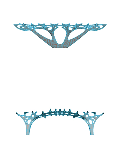
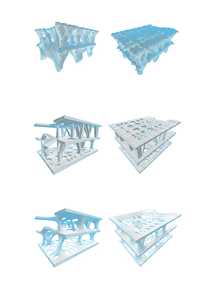
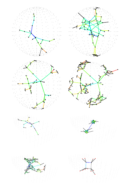
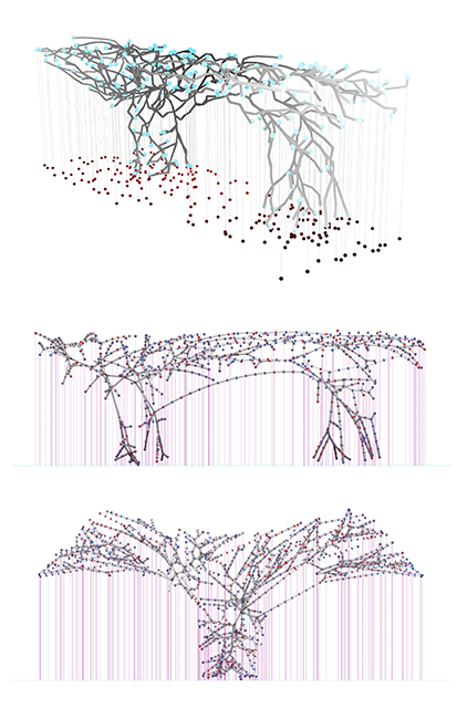
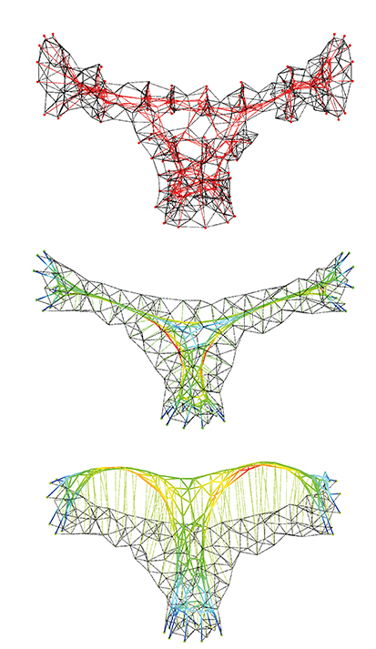
Compression  only graph with minimal deviation from the given graph according to the given loads and self weight.


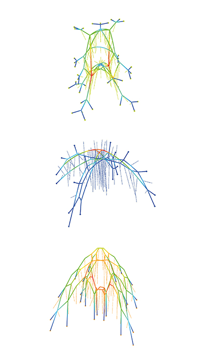
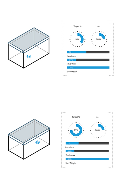
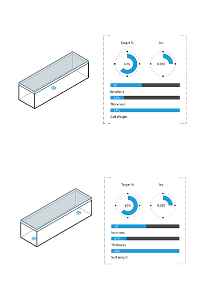
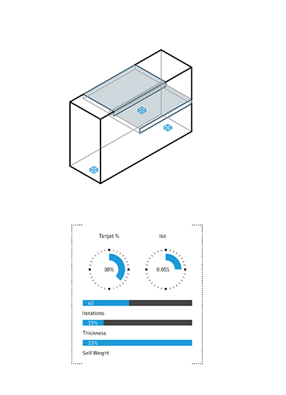
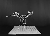
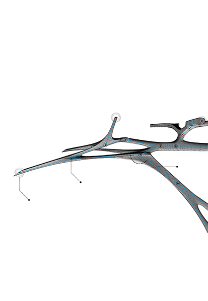
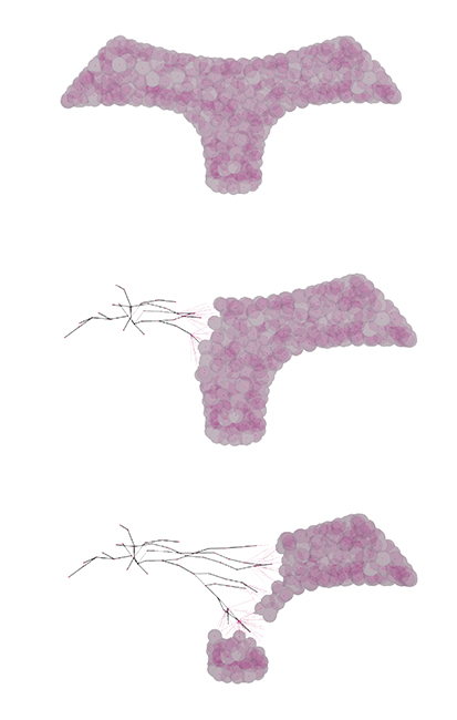
Manually modeled geometric inputs.


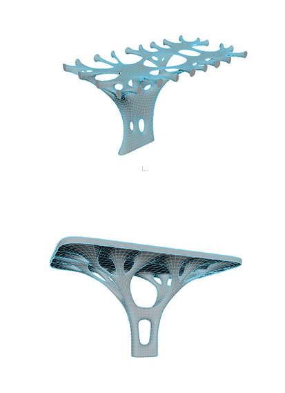
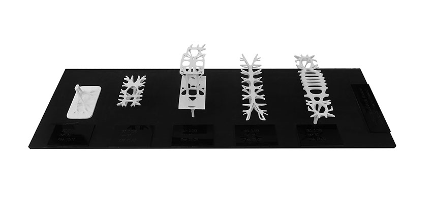
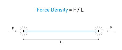
Resultant  compression-only graph where the force density in each member is the same i.e the ratio of force to length in each member is the same.


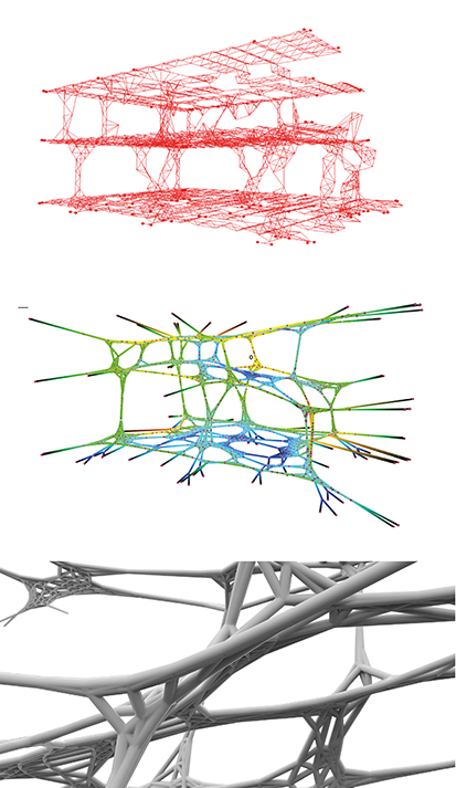
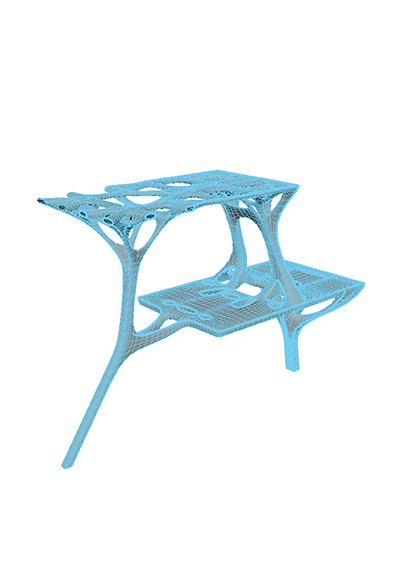
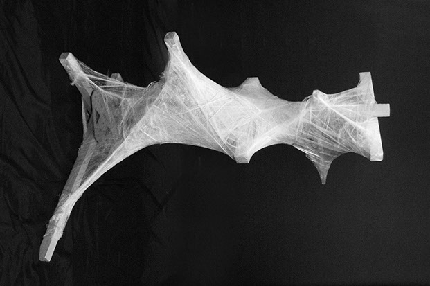
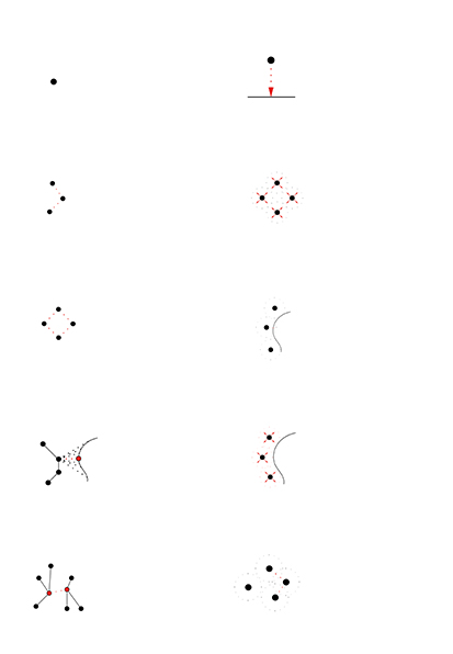
Compression only graphs computed through dynamic relaxation method.


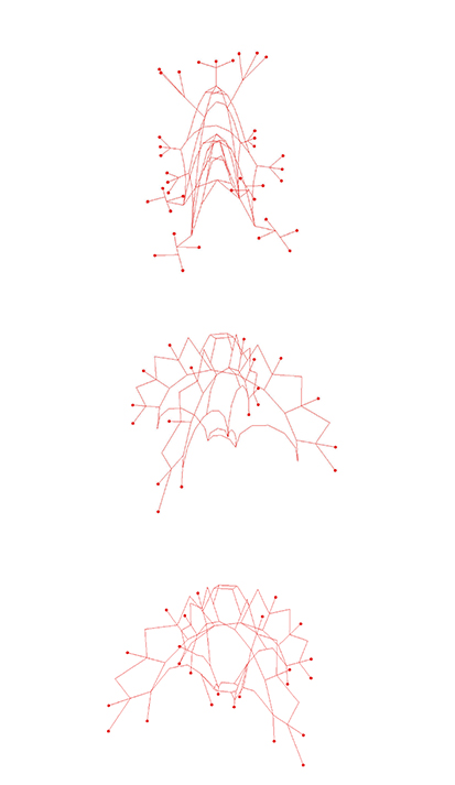
Outline of the Domino House skeletal geometry used as an input to same algortihm.

The dynamic relaxation method has been applied further to the networks obtained through the topology optimisation process in order to achieve only compression graphs. The output networks have been used as guidelines for prototypical architectural elements which have been manually modelled and optimised for 3d printing.